RESEARCH PROPOSAL
DEVELOPMENT OF AN AFFORDABLE AND RELIABLE pH SENSOR
GROUP D
KIRAN CHAND(14)
LIM ZHONGZHI(16)
NG KEEN YUNG(18)
Type of project
-Improve a product or process: Industrial and applied research
e.g. Development of a SMART and GREEN energy system for households
A. QUESTION OR PROBLEM BEING ADDRESSED
Main problem
Maintaining a constant pH is important in many situations. For example, it is necessary to control the pH of an aquarium as certain species of fish can only live within a set pH range. Other fields where controlling the pH is important include hydroponics, fermentation processes like beer and wine production, environmental monitoring of soils, sewage treatment tanks, monitoring of solution and buffers in chemistry laboratories. It is quite difficult to find good and cheap pH sensors. So we have decided to build a cheap and simple pH sensor with easily accessible materials. We will be build it so it can fit in a box with a small display making it portable. Building a small and cheap pH sensor will benefit many people by making pH sensor a widely available product.
Introduction
Acidity is an important factor affecting the conductivity of aqueous solutions (Covington, Bates and Durst, 1985). However, we need to define the acidity. Thus, we have a pH scale and pH.
The concept of pH was first introduced by Danish chemist Søren Peder Lauritz Sørensen at the Carlsberg Laboratory in 1909 (Sørensen, 1909) and revised to the current symbol pH at 1929 to keep it consistent with definition and measurements of electrochemical cells. The meaning of pH has been widely disputed. As Nørby (2000) reported, “Current usage in chemistry is that p stands for “decimal cologarithm of”, as also in the term pKa, used for acid dissociation constants.” (p. 25)
The pH scale is traceable to a set of standard solutions whose pH is established by international agreement (Covington, Bales and Durst, 1985) The pH is defined as the decimal logarithm of the reciprocal of the hydrogen ion activity, aH+, in a solution. 
This definition is adopted because ion-selective probes, which are used to measure pH, respond to activity. Ideally, electrode potential, E, follows the Nernst equation, which, for the hydrogen atom can be expressed as follows:
(where E is measured potential, E0 is the standard electrode potential, R is the gas constant, T is the temperature in kelvin, F is the Faraday Constant. For H+ number of electrons transferred is one)
B. GOALS/EXPECTED OUTCOMES/HYPOTHESES
/ENGINEERING GOAL
- Minimise the size of the pH meter in order to increase the reliability and affordability.
- In order to achieve this goals, we would have to perform repeated experiments and testing to ensure its reliability
- After ensuring its reliability, we would have to go on and make it affordable by minimising cost
- Expand the scope of pH and more research to be conducted.
C. Specifications
- Must fit in a box the size of a typical scientific calculator.
- Must be portable.
- Must be able to run on power from both wall plug and 2 x 9V rectangular battery.
- Must be reliable (Accuracy must match that of commercial sensor)
- Build a reliable digital pH meter for a fraction of the cost of an expensive industrial ph meter or benchtop ph meter.
D. ALTERNATIVES
- Instead of using a pH probe, one can simply use a widely available litmus paper to test for the approximate value of pH.
- This method, however, is not accurate and is not suited for use in industries that require precise values, not vague guesses. Such example would be in the aquatic industry, in which the pH would affect the business greatly (a fish farm would be a good example for this, as some fish are adapted to live in certain pH values)
- Another solution would to be to use the conductivity of the medium to find the pH.
- This is not used as it is overly complicated. However, for people that need to know pH without having to go through the hassle of calibrating the sensor, they can use this method for its versatility. It is called the inferred pH, calculated from the cation conductivity and normal conductivity.
- A third method is a use a organic plant and animals as indicator. For example, certain types of organism will die or exhibit signs of illness when the pH is over a certain level. This method advantages is that it is very cheap and simple. This is because it does not require any special technical know-how and can be implemented instantly. The disadvantage is that it is inhumane and involves sacrificing living organism. This goes against research and moral ethics and thus we would not use it. Even the life of a living organism is a life too.
- The fourth method we considered is to use a pH probe. A typical modern pH probe is a combination electrode, which combines both the glass and reference electrodes into one body. The combination electrode consists of the following parts (see the Figure 1):
- [1] The sensing part of electrode, a bulb made from a specific glass
- [2] Internal electrode, usually silver chloride electrode or calomel electrode
- [3] Internal solution, usually a pH 7 buffered solution of 0.1 mol/L Potassium Chloride(KCl) for pH electrodes or 0.1 mol/L MeCl for pMe electrodes
- [4] When using the silver chloride(AgCl) electrode, a small amount of AgCl can precipitate inside the glass electrode
- [5] reference electrode, usually the same type as 2
- [6] reference internal solution, usually 0.1 mol/L KCl
- [7] junction with studied solution, usually made from ceramics or capillary with asbestos or quartz fiber.
- [8] body of electrode, made from non-conductive glass or plastics.
- The bottom of a pH electrode balloons out into a round thin glass bulb. The pH electrode is best thought of as a tube within a tube. The innermost tube (the inner tube) contains an unchanging 1×10⁻⁷ mol/L Hydrogen Chloride(HCl) solution. Also inside the inner tube is the cathode terminus of the reference probe. The anodic terminus wraps itself around the outside of the inner tube and ends with the same sort of reference probe as was on the inside of the inner tube. It is filled with a reference solution of 0.1 mol/L KCl and has contact with the solution on the outside of the pH probe by way of a porous plug that would serve as a salt bridge
- After taking into consideration the simplicity, price and accuracy, we choose to use a commercially available pH probe and create a pH meter to fully utilize its abilities. The commercially available pH meter accels in all the areas consider. It is simple to use (it only requires calibration to ensure its reliability and usability), it is cheap to use (a pH probe can be had for as low as $9.99 on Amazon) and, most of all, its accuracy is the best out of the all the alternatives considered. Thus, we decided to use a pH probe and make a pH meter to cater to it.
E. EQUIPMENT REQUIRED
- TL082 pH probe x1
- Arduino x1
-Needed to help to retrieve data
- with codes x1
- Voltmeter x1
- Beakers of water (x7)
- Sulphuric acid to make water acidic (100 mL)
- Baking soda(sodium bicarbonate) to make alkaline ( 100ml)
F. METHOD AND PROCEDURES
• Procedures
Construction
- Purchase the materials needed for conducting the experiment from Sim Lim Square. Compile a part list to ensure the correct equipment is bought.
- Conduct a quality check to ensure that all equipment purchased is not defective. If equipment is defective , exchange it immediately.
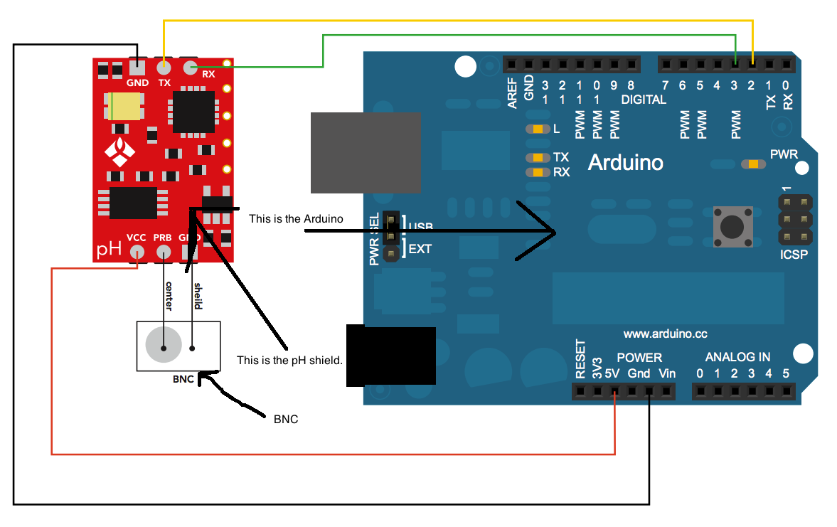
Diagram
- Connect wires as shown below on breadboard.
- Install the code that controls the meter. See Annex 1 for code.
- Prepare three beakers of tap water, using pH buffer solution to change the pH of the different beakers. Prepare another beaker, leave pH unchanged and label it as “Control”. Label the other beakers according to their respective pH.
- Then, we would proceed on to test the our pH meter on the beakers of water.
- Then, we would proceed on to test the reliability of our readings to ensure that our pH meter is accurate. We accomplish this by testing our results against the results of other commercially available pH meters.
- Repeat steps 7 - 8 three times, then average and plot the data on a graph to prevent random errors.
- If we manage to achieve an error margin less than 10%, we would then proceed on to improve on its functionality by making it portable.
- We would try to fit it into a compact package (that includes shrinking the size down to as small as possible)
- We would need to find a portable power source ( for example (2x9V rectangular battery). The Arduino is a relative low power device (9V to 12V) and can be powered with a commercially available batteries. (more convenient)
- If we did not manage to achieve a percentage error below 10%, we would work on calibrating the sensor until we have achieve our goal.
This is the target accuracy of our developed pH sensor compared to the commercial sensor. If data from our sensor closely matches that of commercial sensor, sensor is properly calibrated.
- Document the project and include in videos and pictures
G. Risk and Safety
1. List/identify the hazardous chemicals, activities, or devices that will be used.
-There is a risk of electrocution from mishandling of wires and electricity.
-The acids and alkalis that will be used are corrosive and can cause great harm if mishandled.
2. Identify and assess the risks involved.
-Care must always be taken when handling tools.
-Follow lab rules strictly to prevent injury from incorrect usage of machinery.
-The Arduino board will start to heat up and melt if it is exposed to too high a voltage. So we must be careful and use it with care and caution.
3. Describe the safety precautions and procedures that will be used to reduce the risks.
-Use gloves and proper lab materials when holding the test tubes of acids and alkalis.
-Clean hands thoroughly so we do not contaminate any of the liquids.
-Keep water away from Arduino sets and the voltmeter to prevent electrocution.
4. Describe the disposal procedures that will be used (when applicable).
-Acids and alkalis used in this experiment can be kept for future experimentation. therefore there is no need to dispose of them. However, they must be stored carefully to prevent future accidents.
5. List the sources of safety information
-There will be safety information in the research lab so we will do our best and adhere the rules. Furthermore there will be rules and procedures to use the arduino and the pH kit so we will not mess up the parts.
H. Data Analysis
We will be comparing our pH meter to a store-bought sensor. We will test our meter against the store-bought meter on jars of water that have different acidity as explained under Procedures. We will be using Arduino to help us extract and plot the data on a graph. We will then plot the data from our pH sensor against that of the store-bought sensor. If our sensor is calibrated correctly, the line graph that is plotted should have a gradient very close to one.
I. BIBLIOGRAPHY
Benoit, A. (2013, July 09). pH, Conductivity and TDS. Retrieved from http://environmentalet.hypermart.net/env1221/phcondtds.htm
Covey, J. (2007, November 01). Inferring pH from conductivity and cation conductivity. Retrieved from http://www.power-eng.com/articles/print/volume-111/issue-11/features/inferring-ph-from-conductivity-and-cation-conductivity.html
Covington, A. K.; Bates, R. G.; Durst, R. A. (1985). Retrieved from Pure Appl. Chem. 57 (3): 531–542. http://www.iupac.org/publications/pac/1985/pdf/5703x0531.pdf
Crispa, H. (2006, September 07). Creation of a DIY conductivity meter. Retrieved from http://www.reefcentral.com/forums/showthread.php?t=931044
Nørby, Jens (2000). "The Origin and the Meaning of the Little p in pH". Trends in the Biochemical Sciences 25 (1): 36–37.
Pratical, M. (2011, August 11). DIY EC Probe. Retrieved from http://www.youtube.com/watch?v=0NPtmHdbW3k
Reithmayer, K. (2013, July 10). pH Calibration. Retrieved from http://www.globalw.com/support/calibration.html
Sorensen, S. P. L., Enzymstudien. II, Über die Messung und die Bedeutung der Wasserstoffionenkonzentration bei enzymatischen Prozessen, Biochem. Zeitschr., 1909, vol. 21, pp. 131–304.
Annex 1: Code
#include <LiquidCrystal.h>
LiquidCrystal lcd(13, 5, 2, 3, 1, 0);
#include <avr/eeprom.h> //we'll use this to write out data structure to eeprom
//Our pin definitions
int PHIN = A0;
int HIN = A9;
int TIN = A10;
int GREENLED = 6; //on PWM line :note all these led pins sink not source
int BLUELED = 11; //on PWM line
int REDLED = 12; //normal digital
//LED fade effects
int brightness = 0;
int fadeAmount = 5;
//EEPROM trigger check
#define Write_Check 0x1234
#define VERSION 0x0001
//Oversampling Globals
#define BUFFER_SIZE 16 // For 12 Bit ADC data
volatile uint32_t result[BUFFER_SIZE];
volatile int i = 0;
volatile uint32_t sum=0;
//Rolling average this should act as a digital filter (IE smoothing)
const int numPasses = 20; //Larger number = slower response but greater smoothin effect
int passes[numPasses]; //Our storage array
int passIndex = 0; //what pass are we on? this one
long total = 0; //running total
int pHSmooth = 0; //Our smoothed pHRaw number
//pH calc globals
int pHRaw,tRaw;
float temp, miliVolts, pH,Temp,Hum; //using floats will transmit as 4 bytes over I2C
//Continous reading flag
bool continousFlag,statusGFlag;
//Our parameter, for ease of use and eeprom access lets use a struct
struct parameters_T
{
unsigned int WriteCheck;
int pH7Cal, pH4Cal,pH10Cal;
bool continous,statusLEDG;
float pHStep;
}
params;
void setup()
{
pinMode(GREENLED, OUTPUT);
setupADC(0,100); //Setup our ISR sampling routine analog pin 0 100hz
//Serial1.begin(57600); //Enable basic sesrial commands in base version
eeprom_read_block(¶ms, (void *)0, sizeof(params));
continousFlag = params.continous;
statusGFlag = params.statusLEDG;
if (params.WriteCheck != Write_Check){
reset_Params();
}
// initialize smoothing variables to 0:
for (int thisPass = 0; thisPass < numPasses; thisPass++)
passes[thisPass] = 0;
lcd.begin(20,4);
lcd.print("pH:");
lcd.setCursor(0,1);
lcd.print("Temp:");
lcd.setCursor(0,2);
lcd.print("Humidity:");
}
void loop()
{
//Our smoothing portion
//subtract the last pass
total = total - passes[passIndex];
//grab our pHRaw this should pretty much always be updated due to our Oversample ISR
//and place it in our passes array this mimics an analogRead on a pin
passes[passIndex] = pHRaw;
total = total + passes[passIndex];
passIndex = passIndex + 1;
//Now handle end of array and make our rolling average portion
if(passIndex >= numPasses)
passIndex = 0;
pHSmooth = total/numPasses;
if(statusGFlag)
{
analogWrite(GREENLED, brightness);
// change the brightness for next time through the loop:
brightness = brightness + fadeAmount;
// reverse the direction of the fading at the ends of the fade:
if (brightness == 0 || brightness == 255) {
fadeAmount = -fadeAmount ;
}
}
if(Serial.available() )
{
String msgIN = "";
char c;
while(Serial.available())
{
c = Serial.read();
msgIN += c;
}
processMessage(msgIN);
}
calcpH();
tRaw = LM335ATempConvert(analogRead(TIN),'F');
// The max voltage value drops down 0.00372549 for each degree F over 32F. The voltage at 32F is 3.27 (corrected for zero precent voltage)
float max_voltage = (3.27-(0.00372549*tRaw));
Hum = (((((float)analogRead(HIN)/1023)*5)-.8)/max_voltage)*100;
lcd.setCursor(4,0);
lcd.print(pH);
lcd.print(" ");
lcd.setCursor(6,1);
lcd.print(tRaw);
lcd.print((char)223);
lcd.print('F');
lcd.print(" ");
lcd.setCursor(10,2);
lcd.print(Hum);
if(continousFlag)
{
Serial.print("pHRaw: ");
Serial.print(pHSmooth);
Serial.print(" | ");
Serial.print("pH10bit: ");
Serial.print(analogRead(A0));
Serial.print(" | ");
Serial.print("Milivolts: ");
Serial.println(miliVolts);
Serial.print(" | ");
Serial.print("pH: ");
Serial.println(pH);
Serial.print("Hum: ");
Serial.println(Hum);
delay(1000);
}
delay(30);
}
void calcpH()
{
miliVolts = (((float)pHSmooth/4096)*5)*1000;
temp = ((((5*(float)params.pH7Cal)/4096)*1000)- miliVolts)/5.25; //5.25 is the gain of our amp stage we need to remove it
pH = 7-(temp/params.pHStep);
}
void processMessage(String msg)
{
if(msg.startsWith("L"))
{
if (msg.substring(2,1) == "0")
{
//Status led visual indication of a working unit on powerup 0 means off
statusGFlag = false;
digitalWrite(GREENLED, HIGH);
Serial.println("Status led off");
params.statusLEDG = statusGFlag;
eeprom_write_block(¶ms, (void *)0, sizeof(params));
}
if (msg.substring(2,1) == "1")
{
//Status led visual indication of a working unit on powerup 0 means off
statusGFlag = true;
Serial.println("Status led on");
params.statusLEDG = statusGFlag;
eeprom_write_block(¶ms, (void *)0, sizeof(params));
}
}
if(msg.startsWith("R"))
{
//take a pH reading
calcpH();
Serial.println(pH);
}
if(msg.startsWith("C"))
{
continousFlag = true;
Serial.println("Continous Reading On");
params.continous = continousFlag;
eeprom_write_block(¶ms, (void *)0, sizeof(params));
}
if(msg.startsWith("E"))
{
//exit continous reading mode
continousFlag = false;
Serial.println("Continous Reading Off");
params.continous = continousFlag;
eeprom_write_block(¶ms, (void *)0, sizeof(params));
}
if(msg.startsWith("S"))
{
//Calibrate to pH7 solution, center on this for zero
Serial.println("Calibrate 7");
params.pH7Cal = pHSmooth;
eeprom_write_block(¶ms, (void *)0, sizeof(params));
}
if(msg.startsWith("F"))
{
//calibrate to pH4 solution, recalculate our slope to account for probe
Serial.println("Calibrate 4");
params.pH4Cal = pHSmooth;
//RefVoltage * our deltaRawpH / 12bit steps *mV in V / OP-Amp gain /pH step difference 7-4
params.pHStep = ((((5*(float)(params.pH7Cal - params.pH4Cal))/4096)*1000)/5.25)/3;
eeprom_write_block(¶ms, (void *)0, sizeof(params));
}
if(msg.startsWith("T"))
{
//calibrate to pH10 solution, recalculate our slope to account for probe
Serial.println("Calibrate 10");
params.pH10Cal = pHSmooth;
//RefVoltage * our deltaRawpH / 12bit steps *mV in V / OP-Amp gain /pH step difference 10-7
params.pHStep = ((((5*(float)(params.pH10Cal - params.pH7Cal))/4096)*1000)/5.25)/3;
eeprom_write_block(¶ms, (void *)0, sizeof(params));
}
if(msg.startsWith("I"))
{
//Lets read in our parameters and spit out the info!
eeprom_read_block(¶ms, (void *)0, sizeof(params));
Serial.print("LeoPhi Info: Firmware Ver ");
Serial.println(VERSION);
Serial.print("pH 7 cal: ");
Serial.print(params.pH7Cal);
Serial.print(" | ");
Serial.print("pH 4 cal: ");
Serial.print(params.pH4Cal);
Serial.print(" | ");
Serial.print("pH probe slope: ");
Serial.println(params.pHStep);
}
if(msg.startsWith("X"))
{
//restore to default settings
Serial.println("Reseting to default settings");
reset_Params();
}
}
void reset_Params(void)
{
//Restore to default set of parameters!
params.WriteCheck = Write_Check;
params.statusLEDG = true;
params.continous = false; //turn off continous readings
params.pH7Cal = 2048; //assume ideal probe and amp conditions 1/2 of 4096
params.pH4Cal = 1286; //using ideal probe slope we end up this many 12bit units away on the 4 scale
params.pH10Cal = 2810;//using ideal probe slope we end up this many 12bit units away on the 10 scale
params.pHStep = 59.16;//ideal probe slope
eeprom_write_block(¶ms, (void *)0, sizeof(params)); //write these settings back to eeprom
}
//LM335a temp conversion routine this just makes stuff a lot easier
int LM335ATempConvert(int tempIn, char unitSystem)
{
int KelvinC=273;
int KelvinTemp = (long(tempIn) * 5 * 100) / 1023; // convert
int CelsiusTemp = KelvinTemp-KelvinC;
int FahrenheitTemp = (CelsiusTemp)*(9/5)+32;
int tempOut;
switch(unitSystem){
case 'K':
tempOut = KelvinTemp;
break;
case 'C':
tempOut = CelsiusTemp;
break;
case 'F':
tempOut = FahrenheitTemp;
break;
}
return tempOut;
}
//Our oversampling read functions we will access the hardware directly setting up a counter and a read frequency
//based on the default ADC clock of 250khz, this is all under an Interrupt Service Routine this means we need to keep
//everything contained within as fast as possible especially if we intend on using I2C (clock dragging)
void setupADC(uint8_t channel, int frequency)
{
cli();
ADMUX = channel | _BV(REFS0);
ADCSRA |= _BV(ADPS2) | _BV(ADPS1) | _BV(ADPS0) | _BV(ADATE) | _BV(ADIE);
ADCSRB |= _BV(ADTS2) | _BV(ADTS0); //Compare Match B on counter 1
TCCR1A = _BV(COM1B1);
TCCR1B = _BV(CS11)| _BV(CS10) | _BV(WGM12);
uint32_t clock = 250000;
uint16_t counts = clock/(BUFFER_SIZE*frequency);
OCR1B = counts;
TIMSK1 = _BV(OCIE1B);
ADCSRA |= _BV(ADEN) | _BV(ADSC);
sei();
}
ISR(ADC_vect)
{
result[i] = ADC;
i=++i&(BUFFER_SIZE-1);
for(int j=0;j<BUFFER_SIZE;j++)
{
sum+=result[j];
}
if(i==0)
{
/****DEAL WITH DATA HERE*****/
sum = sum>>2;
//Serial.println(sum,DEC);
//We will simply set a variable here and perform a rolling average on the pH.
pHRaw = sum;
}
sum=0;
TCNT1=0;
}
ISR(TIMER1_COMPB_vect)
{
}
No comments:
Post a Comment